




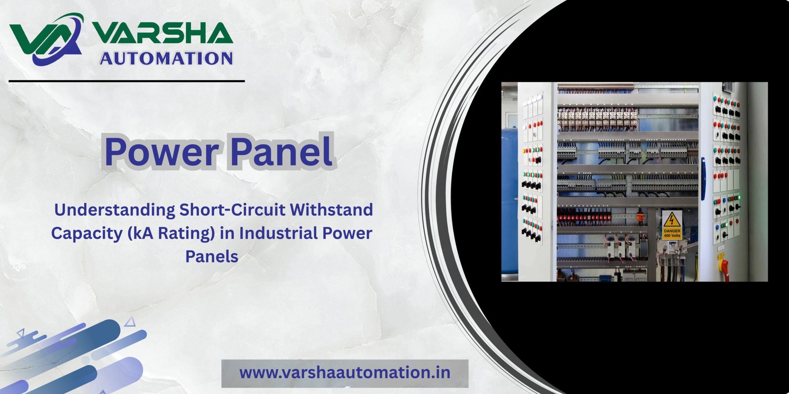
Understanding Short-Circuit Withstand Capacity (kA Rating) in Industrial Power Panels
When designing a low-voltage (LT) power panel or a primary Power Control Center (PCC) for heavy industrial plants, one specific entry in the technical specification datasheet carries paramount safety significance: the Short-Circuit Withstand Capacity, universally known as the kA (Kilo-Amperes) Rating.
While electrical engineers naturally focus on standard operating parameters like continuous current (Amperes) and voltage (Volts), system survivability depends entirely on how many thousands of amperes the panel can safely handle during a catastrophic electrical fault. If a panel’s kA rating falls below the potential fault current delivered by the source transformer, an electrical short circuit can result in total structural destruction and dangerous arc flashes.
Here is a comprehensive engineering breakdown of short-circuit withstand capacity and why it rules industrial switchgear design.
1. What is Short-Circuit Withstand Capacity (kA Rating)?
In plain engineering terms, the kA Rating defines the maximum volume of fault current that an electrical panel assembly—including its enclosure, busbars, supports, and primary switchgear (like ACBs and MCCBs)—can physically withstand without sustaining structural damage or insulation breakdown for a predefined duration (typically 1 second).
Normal Operating Current: For instance, a main incoming panel might be designed to carry a continuous load of 2500A (2.5 kA) under normal operating conditions.
Fault Current: However, when a dead short-circuit occurs (such as a Phase-to-Phase or a Phase-to-Earth fault), the electrical resistance drops close to zero, causing the current to instantly spike to 50,000A (50 kA) or more.
This rating qualifies the panel’s engineering threshold against two distinct destructive phenomena: Thermal Stress and Dynamic/Mechanical Stress.
2. The Twin Destructive Stresses of a Short Circuit
When a massive fault current surges through a panel, it unleashes severe physical forces within milliseconds:
A. Thermal Stress (Thermal Dissipation Forces)
When massive fault currents flow through the internal busbar network, they generate extreme localized heat almost instantly. If the panel’s thermal capacity is miscalculated, this sudden heat spike can melt heat-shrinkable PVC/PVDF phase sleeves, ignite internal insulation components, and crack busbar support blocks (such as SMC or DMC blocks).
B. Dynamic & Mechanical Stress (Electro-Magnetic Force)
Based on electromagnetic principles, when parallel busbar conductors carry massive currents, they generate intense magnetic fields. These fields create intense mechanical forces—both attraction and repulsion—between the phases.
The peak fault current and the physical distance between the parallel busbar phases determine the severity of this force. If the busbar supports are not strategically spaced to counter this heavy mechanical load, the busbars will bend physically out of alignment or rip completely out of their mountings, leading to a catastrophic phase-to-phase explosive arc flash.
3. Standard kA Ratings in Industrial Environments
According to global industrial manufacturing and engineering design benchmarks (such as international IEC 61439 standards), low-voltage switchgear panels are engineered around standardized fault capacity levels:
PCC Panels (Main Incomer): Positioned directly downstream from the primary distribution transformers, these panels face the highest potential fault levels. They are typically engineered for 50kA for 1 Second or 65kA for 1 Second.
MCC Panels (Downstream Distribution): Because these units sit further down the plant floor, the physical impedance of the connecting cables dampens the peak fault current. Consequently, they are generally rated at 35kA for 1 Second or 50kA for 1 Second.
Engineering Excellence at Varsha Automation: Operating out of Ahmedabad, our custom switchgear assemblies are engineered strictly in accordance with certified switchgear testing procedures and rigorous safety standards. To explore our core switchgear manufacturing methodologies, visit our Varsha Automation Home page.
4. How Engineers Determine the Required kA Rating
Before finalizing a panel procurement package or issuing a Request for Quote (RFQ), electrical consultants must perform a dedicated Fault Level Calculation. This study relies heavily on two primary inputs:
Transformer Capacity & Percentage Impedance (%Z): The primary source transformer’s total capacity and its internal percentage impedance dictate the maximum short-circuit current it can physically pump into the system before its own voltage collapses.
Cable Architecture: The length, material (Copper/Aluminum), and cross-sectional area of the cable running from the transformer room to the main LT panel act as electrical resistance, helping to reduce peak fault currents over distance.
If a plant’s fault level study shows an expected worst-case fault profile of 44kA, a panel with a safety threshold of 50kA must be specified to preserve plant safety.
5. System Coordination & Downstream Protection
While reinforcing the physical structural frame of the panel and spacing the busbars correctly handles the fault stresses, the primary switchgear must isolate the issue rapidly. Main incoming Air Circuit Breakers (ACB) use advanced micro-processor release units to trip the panel within milliseconds of detecting a short circuit.
This primary distribution network feeds into specialized downstream controls. For continuous motor protection and automated process safety layouts, explore our advanced engineering frameworks for MCC Panels. Furthermore, if your system incorporates precision automation control systems that require clean power lines completely isolated from large fault disruptions, review our design topologies for PLC Scada Panels.
Certified Power Infrastructure for Your Industry
Specifying an under-rated or poorly coordinated electrical distribution panel exposes your entire plant facility, industrial equipment investment, and shop floor operators to intense risk. Investing in robust short-circuit withstand compliance guarantees long-term operational safety.
Are you sourcing a type-tested, heavy-duty primary distribution system engineered to withstand high kA fault environments? View our comprehensive line of PCC Panels.
Looking to couple heavy power distribution with precise variable motor speed controls and harmonics management? Check out our high-efficiency VFD Panels or consult our engineering technical desk in Ahmedabad today to clear your system drawings.