




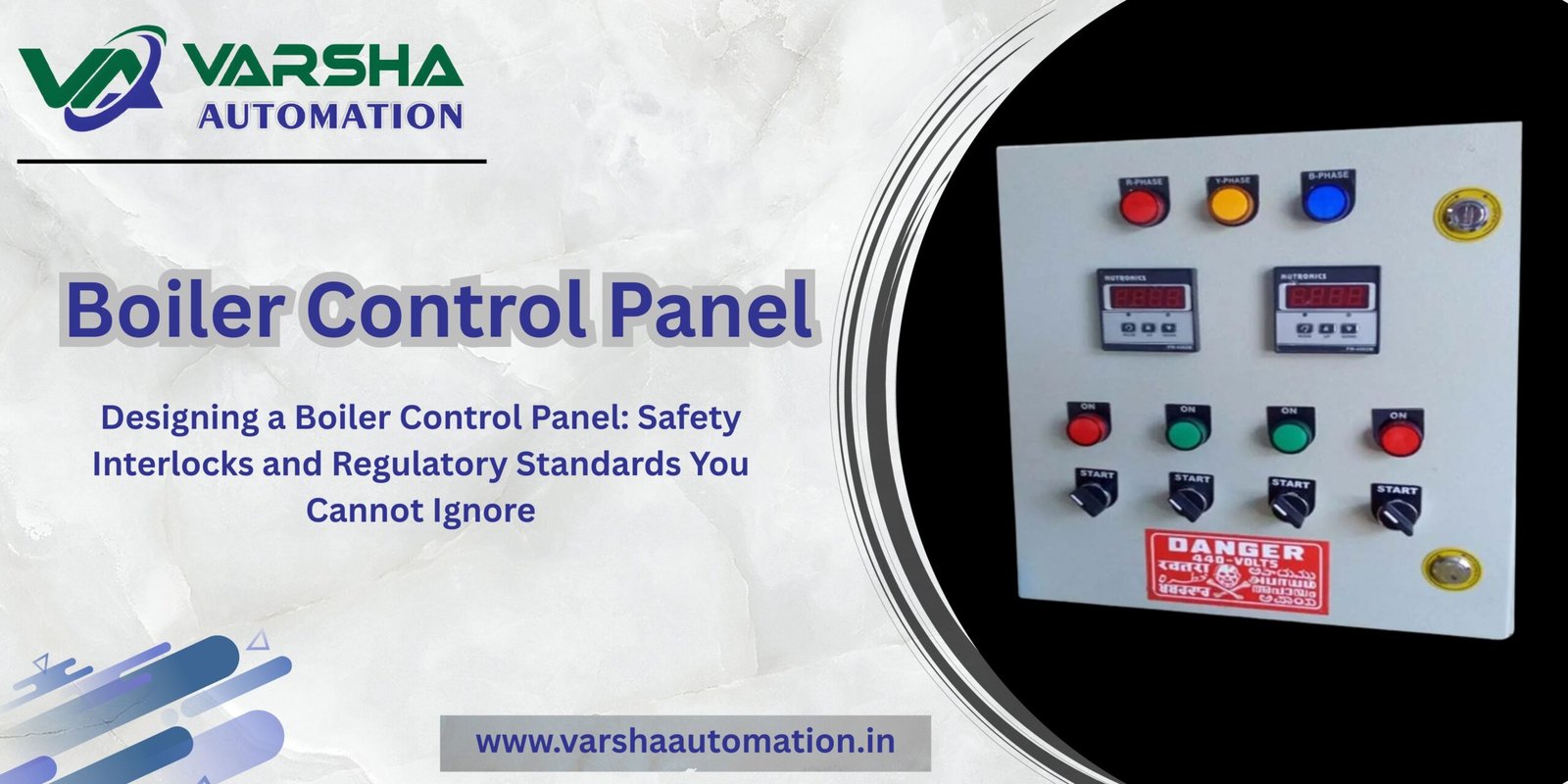
Designing a Boiler Control Panel: Safety Interlocks and Regulatory Standards You Cannot Ignore
In heavy processing industries—such as textile dyeing units, chemical plants, pharmaceutical labs, and food processing facilities—steam generation is a core operational requirement. At the center of this process sits the industrial boiler. Because boilers handle high pressures, high temperatures, and combustible fuels simultaneously, they are inherently high-risk assets.
The Boiler Control Panel acts as the primary safety and operational guardian of this equipment.
Designing this specific automation panel goes beyond basic machine control; it requires strict adherence to international safety codes and absolute precision in setting up hardware-level protection loops. This technical guide covers the essential safety interlocks and design architectures required for industrial boiler automation.
1. The Dual-Architecture Rule: Combustion Control vs. Burner Management
A high-performance boiler panel splits its operations into two distinct functional systems. Mixing these two functions onto a single, non-redundant system introduces severe safety risks.
A. The Combustion Control System (CCS)
The CCS handles the day-to-day efficiency and operational metrics of the boiler. It tracks variable process demands—such as steam pressure fluctuations—and automatically modulates the fuel control valves and combustion air dampers. The primary goal of the CCS is maintaining the correct fuel-to-air ratio to ensure optimal fuel efficiency and low emissions.
B. The Burner Management System (BMS)
The BMS is a dedicated safety system that manages the critical start-up, firing, and emergency shutdown sequences of the burner. Unlike the CCS, which modulates continuously, the BMS operates on a strict binary logic: Safe or Not Safe. If a dangerous operational threshold is breached, the BMS instantly cuts off power to the main fuel safety shutoff valves, forcing a hard safety shutdown (Fuel Trip).
2. Essential Safety Interlocking Sequences
A properly engineered boiler panel utilizes a series of hardwired, sequential safety checks known as a Purge and Permissive Interlock Circuit. The burner will not physically receive fuel until every single safety parameter reports a green status.
Pre-Purge Cycle Interlock: Before ignition can occur, the panel activates the forced draft fan to purge the combustion chamber with fresh air for a set period. This clears out any lingering unburned gas pockets that could cause a violent explosion during spark ignition. The BMS verifies that air pressure switches register adequate airflow before allowing the ignition spark to fire.
Flame Safeguard Interlock: The panel integrates highly sensitive flame scanners (Ultraviolet or Infrared sensors). If the flame scanner fails to detect a continuous pilot or main flame within a critical window (typically 3 to 5 seconds during start-up), the BMS instantly drops power to the fuel line to prevent filling the hot chamber with explosive raw fuel.
Low Water Level Interlock: Running a boiler with low water levels can cause the heat-exchange tubes to overheat and rupture catastrophically. The control panel interfaces with dual-redundant water level sensors. A “Low-Low Water Level” signal triggers an instant, hard lock shutdown of the burner.
3. Advanced Draft and Drum Level Loop Integration
Beyond the immediate safety trips, the boiler panel must smoothly govern complex continuous loops to maintain mechanical equilibrium.
Three-Element Drum Level Control: Simple setups only track the current water level. Advanced boiler automation panels track three distinct elements: steam flow out of the boiler, feed-water flow into the boiler, and the actual drum water level. By anticipating water level changes based on steam demand, the automation system prevents sudden fluctuations and stabilizes boiler pressure.
Draft Pressure Modulation: The panel coordinates the Forced Draft (FD) and Induced Draft (ID) fans to maintain a slightly negative pressure inside the furnace chamber. This structural choice prevents toxic flue gases and flames from escaping outward into the plant environment.
4. Connecting Boiler Systems with Central Plant Automation
An isolated boiler panel limits overall plant visibility. In modern industrial layouts, the localized safety data from the burner system must stream continuously to the main facility control center.
The core data tracking and user graphics layer inside the boiler area tie directly back into centralized management networks. You can read about how these central dashboards are built in our complete engineer’s guide to PLC Scada Panels.
Furthermore, because high-capacity feed-water pumps and draft fans consume significant amounts of electrical energy, standard fixed-speed starters inside the panel are frequently replaced with high-efficiency VFD Panels to optimize motor speeds and lower electrical operating costs.
Secure Your Process Plant with Certified Automation Design
Boiler operations leave no room for compromised engineering or low-grade panel assembly. Implementing robust hardware segregation, certified burner safety relays, and high-reliability instrumentation loops ensures absolute regulatory compliance and continuous plant runtime.
Are you specifying a new boiler control system or looking to replace an obsolete analog burner panel with a modern, safe automation setup? Explore our technical engineering capabilities for PLC Scada Panels or contact our technical engineering desk in Ahmedabad today to receive custom drawings.
Looking to secure the main low-voltage power distribution infrastructure feeding your utility block? View our line of heavy-duty, type-tested PCC Panels and modular MCC Panels.