




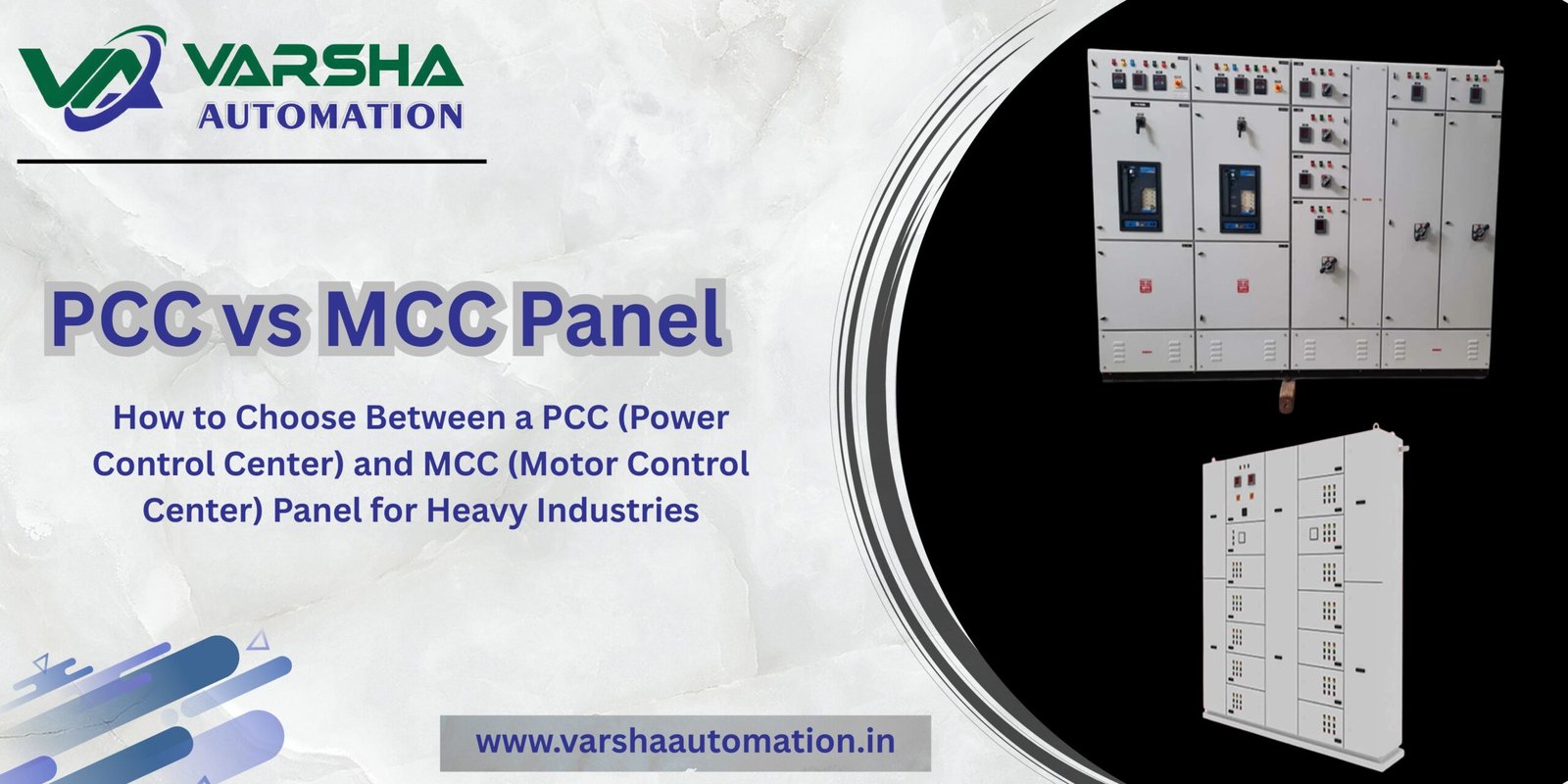
How to Choose Between a PCC (Power Control Center) and MCC (Motor Control Center) Panel for Heavy Industries
In the architecture of a heavy industrial facility—whether it is a chemical processing unit, a textile plant, or a massive manufacturing line—the low-voltage (LT) electrical distribution system forms the backbone of operations. At the heart of this system sit two vital categories of switchgear assemblies: the Power Control Center (PCC) and the Motor Control Center (MCC).
While both assemblies look superficially similar from the outside, they serve completely different electrical functions, house distinct internal switchgear components, and follow different design standards. Confusing their roles during the plant engineering phase can lead to catastrophic failure, poor short-circuit withstand capacity, and inflated project costs.
Industrial Engineering Context: As an Ahmedabad-based manufacturer specializing in high-performance power distribution solutions, we engineer these platforms to withstand the most demanding industrial environments. If you are setting up or upgrading your factory floor infrastructure, you can review our full range of industrial control panels and turnkey solutions directly on our Varsha Automation Home page.
1. Functional Roles: Core Power Distribution vs. Dynamic Motor Control
The most fundamental distinction between a PCC and an MCC lies in its placement and purpose within the electrical hierarchy of the plant.
The Power Control Center (PCC)
A PCC panel serves as the primary distribution hub for the entire facility’s electrical network. It is positioned directly down the line from the main electrical transformers or diesel generator setups. Its primary responsibility is to receive bulk low-voltage power (typically 415V, 3-phase, 50/60Hz) and safely step it down into organized downstream circuits. It protects the overall infrastructure against massive fault currents and distributes power to sub-distribution boards, auxiliary lighting panels, and MCCs.
The Motor Control Center (MCC)
An MCC panel is a specialized, downstream assembly dedicated purely to controlling, protecting, and monitoring electric motors. Rather than merely supplying raw power, an MCC manages the active starting, stopping, reversing, and speed modulation of multiple motor loads from a centralized location. It acts as the bridge between raw plant power and the automated machinery on the shop floor.
When motor operations require precise speed modulation or complex process sequences rather than simple fixed-speed starting, standard MCC starter buckets are typically coupled with dedicated external automation systems. Learn more about how we integrate advanced drives and automation logic by reading our guides on VFD Panels and PLC Scada Panels configurations.
2. Internal Switchgear Components & Fault Ratings
Because these panels manage different types of electrical loads, their internal component configurations and fault withstand profiles vary dramatically.
| Feature / Specification | Power Control Center (PCC) | Motor Control Center (MCC) |
| Typical Ampere Rating | High capacity (800A up to 6300A or higher) | Medium capacity (Generally 100A to 2000A) |
| Primary Incomer Device | Air Circuit Breakers (ACB) | Molded Case Circuit Breakers (MCCB) or Disconnect Switches |
| Downstream Feeders | High-rating MCCBs or SFUs (Switch Fuse Units) | Motor Starters (DOL, Star-Delta, Soft Starters, or VFDs) |
| Protection Hardware | Advanced Microprocessor Relays (Overcurrent, Earth Fault, Under/Over Voltage) | Motor Protection Circuit Breakers (MPCB), Thermal Overload Relays |
| Short-Circuit Withstand | Exceptionally high (Typically 50kA to 85kA for 1 second) | Standard industrial limits (Typically 35kA to 50kA for 1 second) |
3. Structural Design and Form of Separation
The structural layout of these panels is governed heavily by safety codes regarding internal partitioning—known as the Form of Separation (IEC 61439).
PCC Panel Design: Because PCCs handle massive main currents, they are built with rigid structural frames using thick gauge sheet steel. They usually feature Form 4b internal separation. This means the busbar chambers, incoming breaker compartments, and cable termination alleys are completely isolated from each other using metallic barriers. If a fault occurs in one incoming breaker, the blast or arc flash is strictly contained, preventing a total facility blackout.
MCC Panel Design: MCC panels frequently employ modular Drawout Compartments (Form 3b or 4a separation). Each motor starter circuit sits inside its own modular tray or “bucket.” If a single motor starter requires maintenance or component replacement, a plant engineer can safely isolate and slide out that individual tray without de-energizing the entire panel, keeping the rest of the factory running safely.
4. Selection Criteria: Which One Do You Need?
When mapping out your facility’s layout or drawing up a Request for Quote (RFQ), use this simple operational rule:
Choose a PCC Panel if: You need to terminate the main secondary side cables from your utility transformer, integrate your automatic mains failure (AMF) system, feed high-ampere plant subdivisions, or require heavy-duty circuit protection with air circuit breakers.
Choose an MCC Panel if: You are managing a cluster of electric motors (ranging from fractional horsepower to massive kilowatt pumps and compressors), need centralized interlocking with a programmable logic controller (PLC), or require rapid, zero-downtime starter module maintenance.
Pro-Tip for Plant Operators: If your facility utilizes multiple power inputs—such as combining main utility grid feeds with heavy standby diesel generators—neither a standard PCC nor a standalone MCC will handle the phase matching automatically. For these setups, you will need a specialized system configuration. Explore our engineering framework for Synchronize Panels to understand how automated load sharing prevents plant-wide blackouts.
Secure Your Plant Infrastructure with Certified Engineering Layouts
Are you mapping out a new facility blueprint or updating the power reliability of your existing plant floor? Getting your switchgear specifications right during the planning phase prevents expensive site retrofits later.
For heavy-duty primary power distribution, high-kA fault containment, and robust main breaker layouts, view the technical specifications of our heavy industrial PCC Panels.
For smart motor protection, modular drawout starter compartments, and seamless automation interfacing, explore our high-performance MCC Panels or contact our technical engineering desk today for custom drawing approvals.